1. Group assignment:
send a message between two projects.
        #include < WiFi.h >


            const char* ssid = "Vivo V20";

            const char* password = "12345678";


            const char* host = "192.168.98.99"; // Server IP address


            void setup() {

              Serial.begin(115200);

              WiFi.begin(ssid, password);


              while (WiFi.status() != WL_CONNECTED) {

                delay(1000);

                Serial.println("Connecting to WiFi...");

              }


              Serial.println("Connected to WiFi");

              Serial.println("Type your message and press Enter to send:");

            }


            void loop() {

              if (Serial.available()) {

                String msg = Serial.readStringUntil('\n');

                sendMessage(msg);

              }

            }


            void sendMessage(String msg) {

              WiFiClient client;


              if (!client.connect(host, 80)) {

                Serial.println("Connection to server failed");

                return;

              }


              client.println(msg);

              Serial.println("Sent: " + msg);


              while (client.connected()) {

                if (client.available()) {

                  String response = client.readStringUntil('\n');

                  Serial.println("Received: " + response);

                  break;

                }

              }


              client.stop();

            }
Libraries and Variables:
#include < WiFi.h >: Includes the library for WiFi functions.
ssid and password: WiFi credentials for connecting to the network.
host: IP address of the server to communicate with.
setup() Function:
Initializes the serial communication at a baud rate of 115200.
Connects to the specified WiFi network and waits until the connection is established.
Once connected, it prints messages indicating successful connection and readiness to send messages.
loop() Function:
Continuously checks if there's input available in the serial monitor.
Reads the input until a newline character and calls sendMessage() to send it to the server.
sendMessage(String msg) Function:
Creates a WiFi client and attempts to connect to the server on port 80.
If the connection fails, it prints an error message.
If successful, it sends the message to the server.
Waits for a response from the server, prints it, and then closes the connection.
        #include < WiFi.h >


            const char* ssid = "Vivo V20";

            const char* password = "12345678";


            WiFiServer server(80);


            void setup() {

              Serial.begin(115200);

              WiFi.begin(ssid, password);


              while (WiFi.status() != WL_CONNECTED) {

                delay(1000);

                Serial.println("Connecting to WiFi...");

              }


              Serial.println("Connected to WiFi");

              server.begin();

              Serial.println("Server started");

              Serial.print("IP Address: ");

              Serial.println(WiFi.localIP());

            }


            void loop() {

              WiFiClient client = server.available();


              if (client) {

                Serial.println("Client connected");

                while (client.connected()) {

                  if (client.available()) {

                    String msg = client.readStringUntil('\n');

                    Serial.println("Received: " + msg);

                    client.println("Message received: " + msg);

                  }

                }

                client.stop();

                Serial.println("Client disconnected");

              }

            }
1. Include statement:
#include < WiFi.h >
This line includes the WiFi library. This library provides functions and functionalities for interacting with WiFi modules connected to the microcontroller.
2. Constant variable declarations:
const char* ssid = "Vivo V20";
const char* password = "12345678";
two constant character pointers are declared:
ssid: Stores the name of the WiFi network to connect to (in this case, "Vivo V20").
password: Stores the password for the WiFi network (in this case, "12345678").
3. WiFi server object:
WiFiServer server(80);
This line creates a WiFiServer object named server. This object will be used to listen for incoming connections on port 80, which is the standard port for HTTP communication.
4. setup() function:
void setup() {
Serial.begin(115200);
WiFi.begin(ssid, password);
while (WiFi.status() != WL_CONNECTED) {
delay(1000);
Serial.println("Connecting to WiFi...");
}
Serial.println("Connected to WiFi");
server.begin();
Serial.println("Server started");
Serial.print("IP Address: ");
Serial.println(WiFi.localIP());
The setup() function is called once when the program starts. Here's what each line does:
Serial.begin(115200): Initializes the serial communication at a baud rate of 115200. This allows the program to print messages to a serial monitor for debugging purposes.
WiFi.begin(ssid, password): Attempts to connect to the WiFi network specified by ssid and password.
The while loop keeps trying to connect to WiFi until a successful connection is established (WL_CONNECTED). Inside the loop:
delay(1000): Pauses the program for 1 second.
Serial.println("Connecting to WiFi..."): Prints a message to the serial monitor indicating the connection attempt.
Serial.println("Connected to WiFi");: Prints a message to the serial monitor confirming a successful WiFi connection.
server.begin(): Starts the WiFi server on port 80.
Serial.println("Server started");: Prints a message to the serial monitor indicating the server is started.
Serial.print("IP Address: ");: Prints "IP Address: " to the serial monitor.
Serial.println(WiFi.localIP());: Prints the microcontroller's IP address assigned by the WiFi network to the serial monitor.
5. loop() function:
void loop() {
WiFiClient client = server.available();
if (client) {
Serial.println("Client connected");
while (client.connected()) {
if (client.available()) {
String msg = client.readStringUntil('\n');
Serial.println("Received: " + msg);
client.println("Message received: " + msg);
}
}
client.stop();
Serial.println("Client disconnected");
}
}
The loop() function runs repeatedly after the setup() function finishes. Here's what each line does inside the loop:
WiFiClient client = server.available(): Checks if there's a client trying to connect to the server. If a client is available, it creates a WiFiClient object named client to manage the connection.
The if (client) block checks if a client is connected. If so, the following code executes:
Serial.println("Client connected");: Prints a message to the serial monitor indicating a client connection.
The inner while loop keeps running as long as the client is connected:
if (client.available()): Checks if there's data available from the client.
String msg = client.readStringUntil('\n'): Reads a string from the client until a newline character (\n) is encountered and stores it in the msg variable.
Serial.println("Received: " + msg);: Prints a message to the serial monitor indicating received data along with the content.
I learned two way communication between two XIAO-ESP32-C3 microcontroller using serial communication.
Here, I refer the YouTube Video for two communication between the microcontrollers. There are two nodes, one XIAO-ESP32-C3 microcontroller is Transmitter to transmit the signals and another is Receiver to receive the signal. Following are the steps -
Transmitter Node -
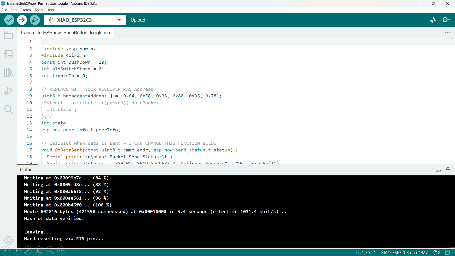
Firstly, I uploaded the code of Transmitter node in the one XIAO-ESP32-C3 using Arduino IDE.
Code -
#include < esp_now.h>

#include < WiFi.h>

const int pushDown = 10;

int oldSwitchState = 0;

int lightsOn = 0;


// REPLACE WITH YOUR RECEIVER MAC Address

uint8_t broadcastAddress[] = {0x64, 0xE8, 0x33, 0x80, 0x95, 0x78};

/*struct __attribute__((packed)) dataPacket {

  int state ;

};*/

int state ;

esp_now_peer_info_t peerInfo;


// callback when data is sent - I CAN CHANGE THIS FUNCTION BELOW

void OnDataSent(const uint8_t *mac_addr, esp_now_send_status_t status) {

  Serial.print("\r\nLast Packet Send Status:\t");


  Serial.println(status == ESP_NOW_SEND_SUCCESS ? "Delivery Success" : "Delivery Fail");

}


void setup() {

  pinMode(pushDown,INPUT);

  // Init Serial Monitor

  Serial.begin(115200);


  // Set device as a Wi-Fi Station

  WiFi.mode(WIFI_STA);


  // Init ESP-NOW

  if (esp_now_init() != ESP_OK) {

    Serial.println("Error initializing ESP-NOW");

    return;

  //pinMode(pushDown, INPUT);

  }


  // Once ESPNow is successfully Init, we will register for Send CB to

  // get the status of Trasnmitted packet

  esp_now_register_send_cb(OnDataSent);


  // Register peer

  memcpy(peerInfo.peer_addr, broadcastAddress, 6);

  peerInfo.channel = 0;

  peerInfo.encrypt = false;


  // Add peer

  if (esp_now_add_peer(&peerInfo) != ESP_OK){

    Serial.println("Failed to add peer");

    return;

  }

}


void loop() {


  // dataPacket packet;


  //packet.state = digitalRead(pushDown);

  //Serial.println(lightsOn);

   state = digitalRead(pushDown); // read the pushButton State

 if (state != oldSwitchState) // catch change

 {

 oldSwitchState = state;

 if (state == HIGH)

 {

 // toggle

 lightsOn = !lightsOn;

 }

 }

 Serial.println(lightsOn);


  esp_now_send(broadcastAddress, (uint8_t *) &lightsOn, sizeof(lightsOn));


  delay(30);


}
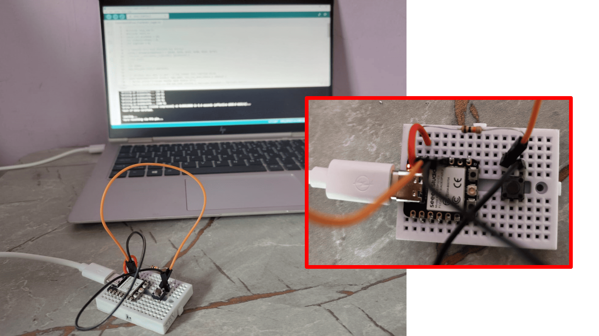
Code Explaination with Connections -
In this setup, a push button is connected to a Xiao ESP32-C3 microcontroller for two-way communication using ESP-NOW. The push button has one pin connected to the D10 pin of the Xiao ESP32-C3 microcontroller, and this connection is grounded through a pull-up resistor to ensure the pin reads a stable state. The other pin of the push button is connected to the 3V3 pin to provide the necessary voltage. The code initializes the serial monitor for debugging and sets the device as a Wi-Fi station. It initializes ESP-NOW and registers a callback function `OnDataSent` to check the status of the data sent. It also registers the receiver's MAC address and adds the peer information required for ESP-NOW communication.
In the main loop, the code reads the state of the push button connected to D10. If the state of the push button changes, it toggles the value of the `lightsOn` variable, which indicates whether the LED should be on or off. This state is then sent to the receiver microcontroller using ESP-NOW. The `esp_now_send` function sends the current state of the `lightsOn` variable to the specified MAC address of the receiver. The loop includes a small delay to debounce the button press and ensure reliable state detection. This setup allows the push button to control an LED or other components connected to the receiver microcontroller, enabling a simple form of remote control through Wi-Fi communication.
Receiver Node -
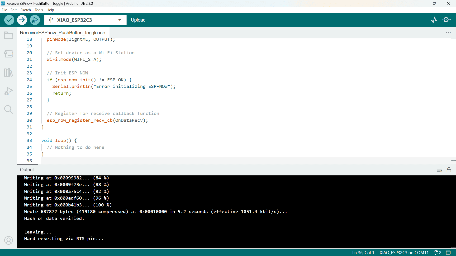
Now, I uploaded the code of Receiver node in the another XIAO-ESP32-C3 using Arduino IDE.
Code -
#include < esp_now.h>

    #include < WiFi.h>

    const int lightME = 10;


    int lightsOn;


    // Callback function that will be executed when data is received

    void OnDataRecv(const uint8_t *mac_addr, const uint8_t *incomingData, int len) {

      memcpy(&lightsOn, incomingData, sizeof(lightsOn));

      Serial.print("button: ");

      Serial.println(lightsOn);

      digitalWrite(lightME, lightsOn);

    }


    void setup() {

      // Initialize Serial Monitor

      Serial.begin(115200);

      pinMode(lightME, OUTPUT);


      // Set device as a Wi-Fi Station

      WiFi.mode(WIFI_STA);


      // Init ESP-NOW

      if (esp_now_init() != ESP_OK) {

        Serial.println("Error initializing ESP-NOW");

        return;

      }


      // Register for receive callback function

      esp_now_register_recv_cb(OnDataRecv);

    }


    void loop() {

      // Nothing to do here

    }
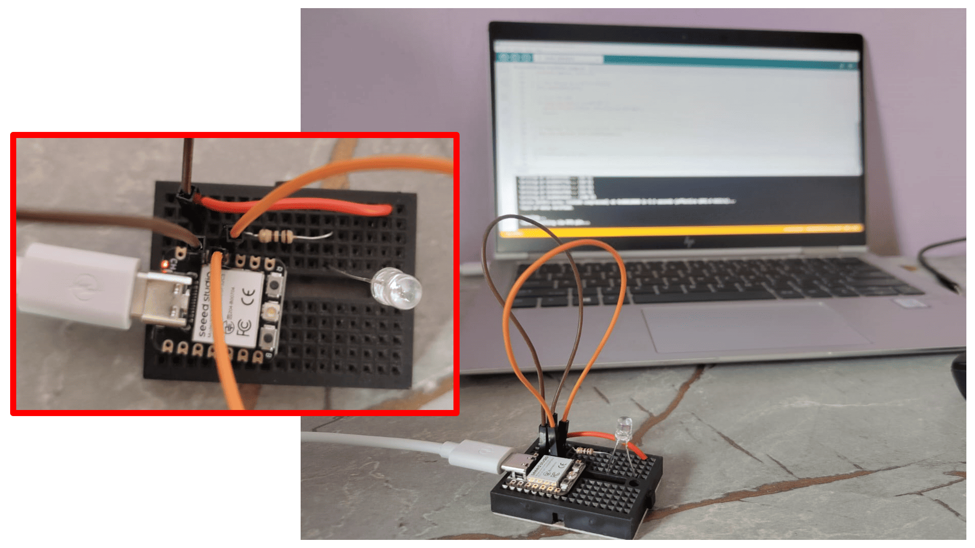
Code Explaination with Connections -
In this setup, an LED is connected to the Xiao ESP32-C3 microcontroller to receive data via ESP-NOW and control the LED's state based on the received data. The cathode (negative leg) of the LED is connected to the ground (GND) pin, while the anode (positive leg) is connected to the D10 pin through a resistor, which limits the current to protect the LED. The code begins by including the necessary `esp_now.h` and `WiFi.h` libraries for ESP-NOW and Wi-Fi communication. The `lightME` constant is defined to specify the pin connected to the LED.
In the `setup` function, the serial monitor is initialized for debugging purposes, and the D10 pin is configured as an output to control the LED. The ESP32 is set to Wi-Fi station mode using `WiFi.mode(WIFI_STA)`. The ESP-NOW protocol is initialized, and if it fails, an error message is printed to the serial monitor. Upon successful initialization, a callback function `OnDataRecv` is registered to handle incoming data. This callback function copies the received data into the `lightsOn` variable, prints the button state to the serial monitor, and sets the LED's state accordingly using `digitalWrite`. The `loop` function remains empty as all the action happens in the callback function, triggered by incoming data. This setup allows the Xiao ESP32-C3 to receive data from another ESP-NOW device and control the LED based on the received information.

Finally, here I got the output that one Xiao ESP32-C3 microcontroller with a push button sends the button state via ESP-NOW to another Xiao ESP32-C3 microcontroller, which then controls an LED based on the received state. When the button is pressed, the state is sent wirelessly, and the receiving microcontroller toggles the LED on or off accordingly, providing remote control of the LED through wireless communication.
In this setup, the ESP-NOW protocol is used to facilitate wireless communication between two Xiao ESP32-C3 microcontrollers. ESP-NOW is a low-power, connectionless Wi-Fi protocol developed by Espressif that enables devices to communicate directly with each other without needing a traditional Wi-Fi network. It supports low-latency, peer-to-peer communication, making it ideal for applications requiring fast and efficient data exchange. The protocol allows devices to send short, encrypted packets to multiple peers simultaneously. In this specific setup, one microcontroller is configured with a push button and sends the button's state via ESP-NOW to the other microcontroller. The receiving microcontroller then controls an LED based on the received state, toggling it on or off accordingly. This direct communication is achieved by setting the devices to Wi-Fi Station mode, allowing them to exchange data quickly and efficiently without the need for an access point or router.
Code : client.ino.
Code : server.ino.
Code : Receiver.ino.
Code : Transmitter.ino.